With that number defined, we evaluated drives across multiple manufacturers. Only one platform could operate at that voltage as a standard product: the Nidec / Control Techniques Unidrive M700 series, a drive commonly deployed in elevator applications, where low-voltage DC bus operation is a routine requirement when utility power loss is experienced. This same architecture, applied here, solved a problem that had no clean solution elsewhere in the market.
Servo Positioning System for a Vacuum Casting Mold Application
How Applied Motion Systems engineered a motion control solution for a vacuum environment where standard servos couldn’t operate, and standard assumptions didn’t apply
The Problem: Motion Control Inside a Vacuum, Where the Normal Rules Don’t Apply
Deploying servo positioning systems in a vacuum environment isn’t a matter of selecting the right servo system from a catalog. The physics change, and the assumptions that underpin standard motor selection, heat dissipation, electrical conductivity, and material stability, stop being reliable the moment that air pressure drops.
This project involved a casting mold positioning system. The application required precise X- and Y-axis mold positioning within a vacuum chamber under an argon-shielding gas environment. Argon was used to prevent metal oxidation during the casting process. It also made the electrical design problem a bit more challenging.
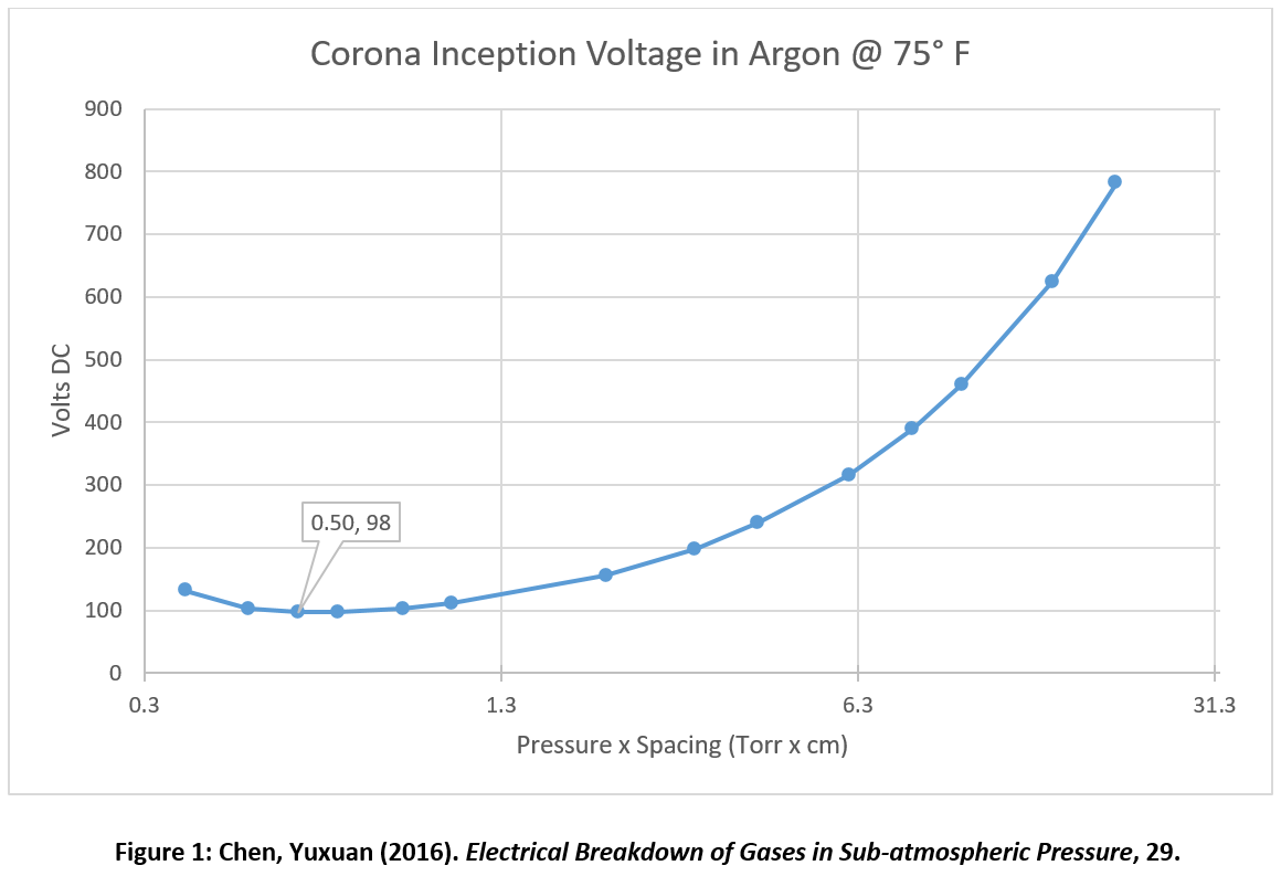
The core issue was corona arcing. In a low-pressure environment, the rarified atmosphere ionizes easily. When the voltage between exposed motor conductors exceeds the Corona Inception Voltage (CIV) for that environment, current arcs. Motor winding insulation erodes. Turn-to-turn short circuits follow. The motor fails.
Argon, with its smaller molecules, lowers the CIV further compared to air at the same pressure. That meant the operating voltage ceiling for this application wasn’t just lower than standard, it was lower than what most industrial servo drives are designed to handle.
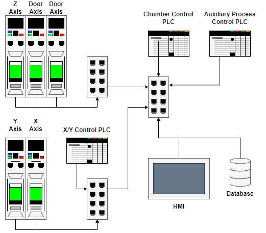
The facility also needed a motion control solution that could work across all axes of the system: mold positioning inside the vacuum, plus ladle and chamber door axes operating at atmospheric conditions outside it. A fragmented drive platform with different hardware, interfaces, and spares was far from optimum. The system needed to be maintainable and cost-effective by the team running it, not just the engineers who built it.
The ask was technically precise: keep all conductor voltages below the arcing threshold, select motors that could operate under vacuum heat dissipation constraints, and integrate cleanly with an existing Rockwell PLC control platform.
The Solution: Calculated First, Specified Second
Before we touched a component catalog, we did the math.
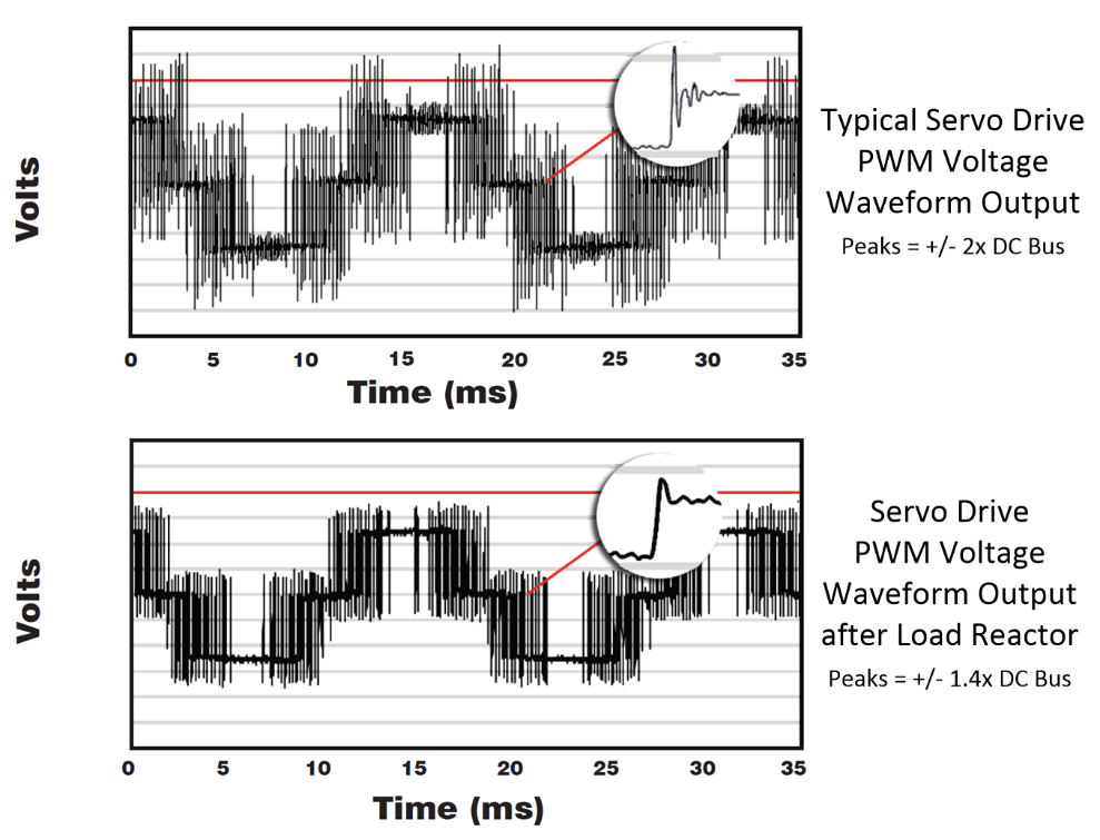
Using Paschen’s Law, which defines breakdown voltage as a function of pressure and conductor separation distance, we established a safe maximum DC bus voltage for the argon vacuum environment. That calculation had to account for more than the static CIV. Servo drives use IGBTs that switch at high frequencies to synthesize sinusoidal current waveforms, and those switching events produce voltage spikes at the motor stator that can reach twice the DC bus level. A load reactor was added to the system to dampen those spikes, and the factor of safety was applied on top of that.
The result: a maximum DC bus voltage of 63 volts.
Motor selection followed the same engineering focused approach using first principles. An electric motor’s continuous torque capacity in a vacuum is reduced significantly. Convective heat transfer doesn’t exist without air, so the motor can’t shed heat the way it would in normal atmospheric conditions. We derated the continuous torque requirement by a factor of five, then matched that against actual move trajectories and RMS torque loading. A semi-customizable motor with a low-voltage winding configuration fit the velocity and torque requirements without requiring a fully custom build. Resolvers were selected for position feedback, simpler and more robust than encoders in difficult environmental conditions, and appropriate for the duty cycle.
On the integration side, the M700’s “PLC Controlled Motion” capability handled the Rockwell interface directly. Pre-engineered add-on instructions within Studio 5000 meant the PLC logic for drive control was straightforward to implement. Axes outside the vacuum, the ladle, the pour axis, and the chamber door actuators, ran on the same drive platform at standard voltages, giving the facility a common hardware stack, common spares, and a uniform software interface across the entire system.
The same drive family that solved the hardest constraint in the project also simplified everything around it.
The Results: What Actually Changed
Corona arcing eliminated by design. The 63-volt DC bus limit kept all conductor voltages below the CIV for the argon vacuum environment throughout the casting process. The failure mode that makes vacuum motor deployments risky – arcing, winding erosion, and unplanned motor replacement – was addressed at the specification stage, not discovered after commissioning.
Motor thermal performance validated under vacuum conditions. The five-to-one derating approach provided the motors with appropriate continuous torque headroom to meet the heat-dissipation constraints of vacuum operation. Selecting for the actual RMS torque demand, rather than nameplate ratings, ensured the motors weren’t undersized for the environment they were operating in.
Single drive platform across all axes. M700 drives handled both the low-voltage vacuum axes and the standard atmospheric axes — different operating conditions, same hardware family. Common spares. Consistent interface. The kind of control system integration that makes long-term maintenance practical for the facility team rather than dependent upon the original integrator.
Integration with Rockwell PLC completed without custom development. The “PLC Controlled Motion” package provided pre-built logic building blocks that worked within the existing Studio 5000 environment. A technically complex application — multi-axis positioning, vacuum-rated hardware, semi-custom motors — connected to the control platform simply and elegantly.
A repeatable methodology for a problem category that isn’t going away. Vacuum motion control requirements appear across aerospace tooling, ion beam welding, laser sintered powdered metal 3D printing, and precision casting. The engineering framework developed here, CIV calculations, voltage ceiling derivation, and derated thermal modeling, applies to future applications in the same way – AMS’s first principles based engineering framework produces reliable results every time.
You can download this case study here.
About Applied Motion Systems
AMS is a systems integrator and machine builder. Our work is in motion control and industrial automation systems, across paper converting, web handling equipment, aerospace tooling, and applications most companies haven’t tried before.
We design for the operator who runs the machine every shift, not just the engineer who specifies it. And we build with the long view in mind, designing systems that serve operators reliably five, ten, and twenty years after commissioning, because that is when the value of building it right becomes clear.
If you are working through a motion control challenge in a difficult environment, we would welcome the conversation.
start the conversation
All of our collaborations begin with an open dialogue.
Get in touch with us using this simple form, and a member of our team will follow up with you soon.